Using TARA Studio Application
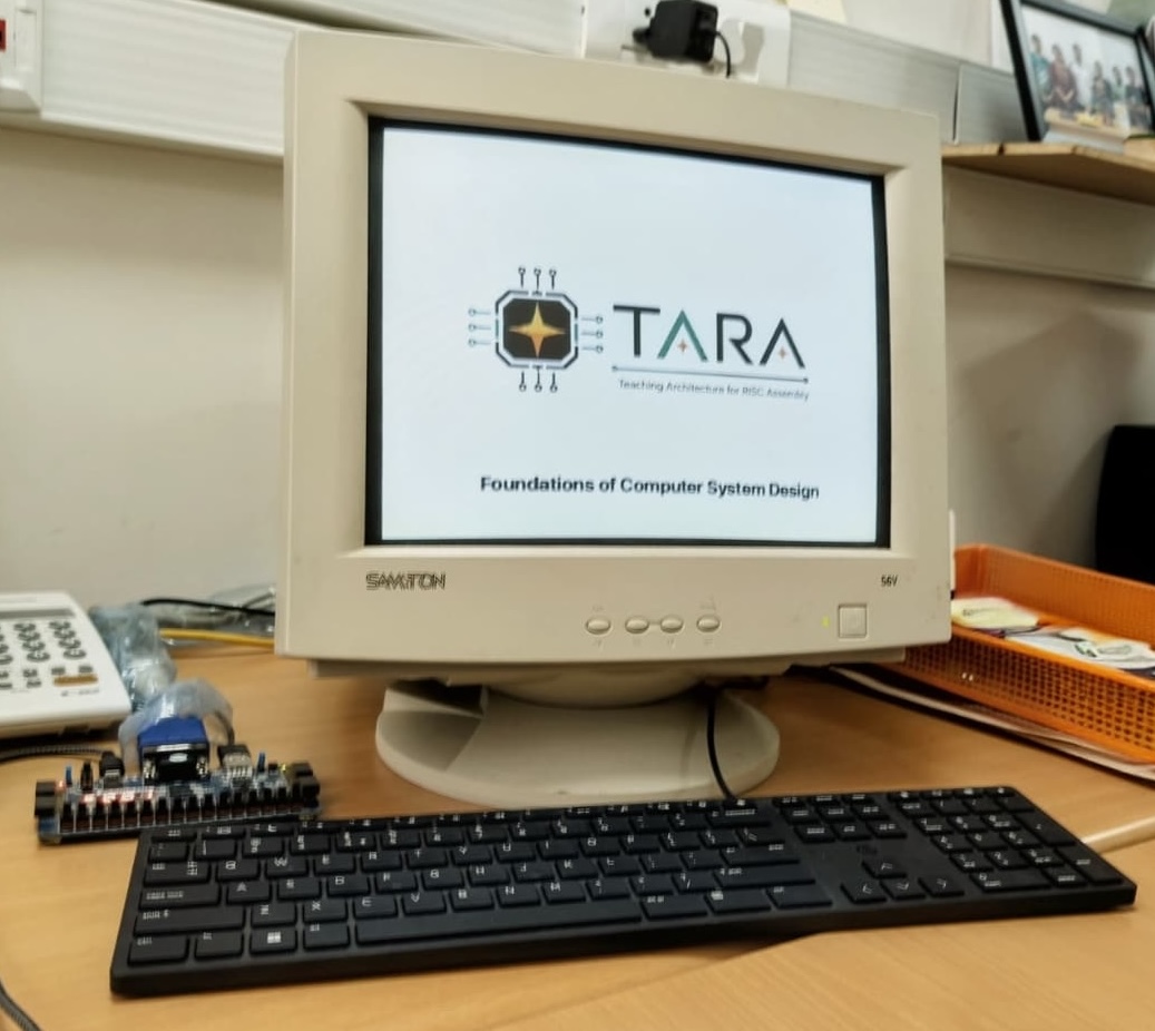
TARA Studio supports writing, assembling, executing, and inspecting programs for the TARA (Teaching Architecture for RISC Assembly) platform. TARA is a pedagogical 16-bit CPU ISA developed and maintained by Dr. Ayon Chakraborty. The ISA is taught as part of CS2300: Foundations of Computer System Design at IIT Madras, where students learn to build a simple, multi-cycle, non-pipelined, fully functional processor from the ground up. TARA can run a range of assembly programs, from basic examples such as array sorting and prime-number generation to simple games such as ping pong, snake and Flappy Bird, all written in tara assembly. It also includes memory-mapped support for VGA display output and keyboard input. TARA has been successfully tested on real hardware (FPGA) along with a VGA display and keyboard.
When you open the TARA Studio desktop application, you will find two tabs across the top. The first, TARA CPU Simulator, is the software CPU you will spend most of this manual with: type in some assembly, watch it run one instruction at a time and play around the registers and memory as it goes. The second, TARA FPGA Tool, can talk to an actual TARA processor running on an FPGA (Basys3 board was tested) over a plain USB cable, or attach to the simulator's own memory when hardware is not available. In both modes you can peek at memory live and send your own programs to the selected target (see TARA on Real Hardware).
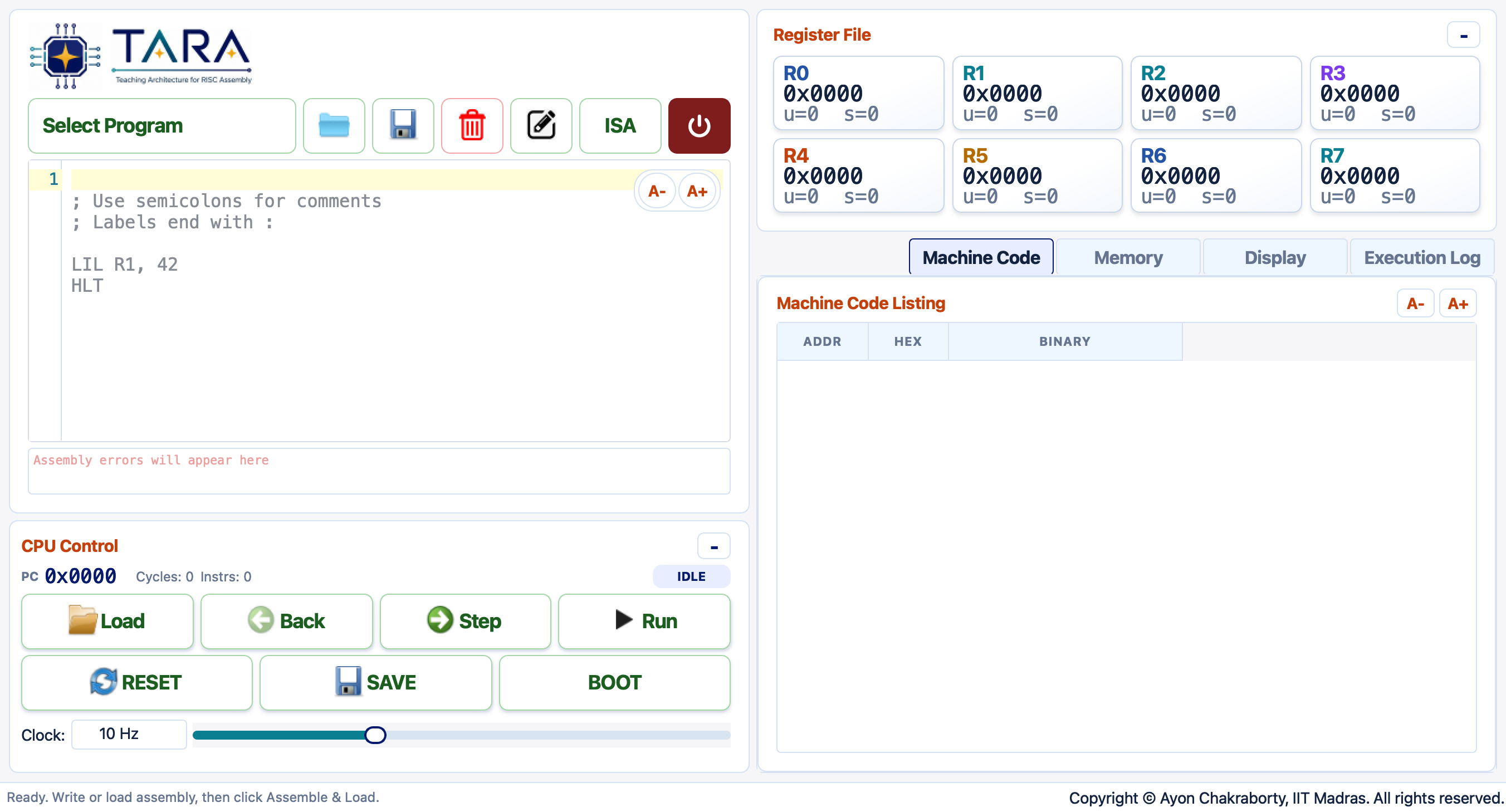
TARA Studio on launch, with the TARA CPU Simulator tab selected — assembly editor on the left, register file and panel tabs on the right. The TARA FPGA Tool tab sits alongside it at the top.
Installation
The TARA Studio desktop application, taracpu, is a standard Python package on PyPI.
Installing it is just three steps — create an environment, pip install,
and run. You do not need PyCharm, VSCode,
or any other IDE. The recommended workflow uses a dedicated conda or venv environment
so it stays isolated from your other Python projects.
Using conda (recommended — Anaconda / Miniconda)
Run this block once to set everything up:
conda create -n taracpu-cs2300 python=3.11 -y
conda activate taracpu-cs2300
pip install taracpu
Then launch the simulator:
taracpuconda activate taracpu-cs2300
taracpuUsing venv (no Anaconda required)
macOS / Linux:
python3 -m venv taracpu-cs2300
source taracpu-cs2300/bin/activate
pip install taracpu
taracpu
Windows (PowerShell):
python -m venv taracpu-cs2300
taracpu-cs2300\Scripts\Activate.ps1
pip install taracpu
taracpu~/.taracpu/ (created automatically on first launch).
Quick Start
The fastest way to see the simulator in action:
- Launch it: run
taracpuin your terminal (after the one-time install above), or just open the web version. - In the Assembly Editor, paste or type a program (or pick one from the Select Program dropdown).
- Click Load to assemble the code and write it into memory.
- Click Step repeatedly to execute one instruction at a time — watch the registers, listing highlight, and decode panel update.
- Click Run to run continuously. The button becomes Stop while running.
- When execution reaches
HLT, check the result register.
Simulator Walkthrough: Bubble Sort
This recording shows the complete simulator workflow: selecting and loading
Bubble Sort, running it, and watching the Memory heatmap change as the
256-byte array at 0x0400 is gradually sorted.
Try It: Factorial 6! = 720
; Factorial using MUL: 6! = 720
LIL R1, 6       ; n = 6
LIL R3, 1       ; result = 1
MOV R4, R1      ; factor = n
outer: BZ R4, done
MUL  R3, R3, R4
ADDI R4, -1
JMP  outer
done: HLT       ; R3 = 720 = 0x02D0
Paste this, click Load, then Run. When halted, R3 will show 0x02D0 (720).
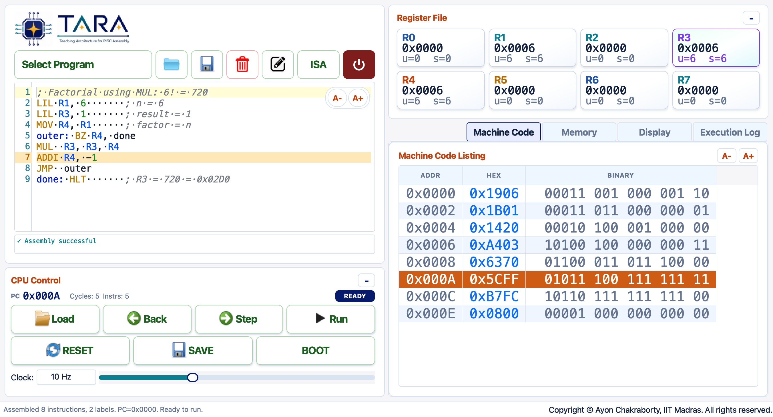
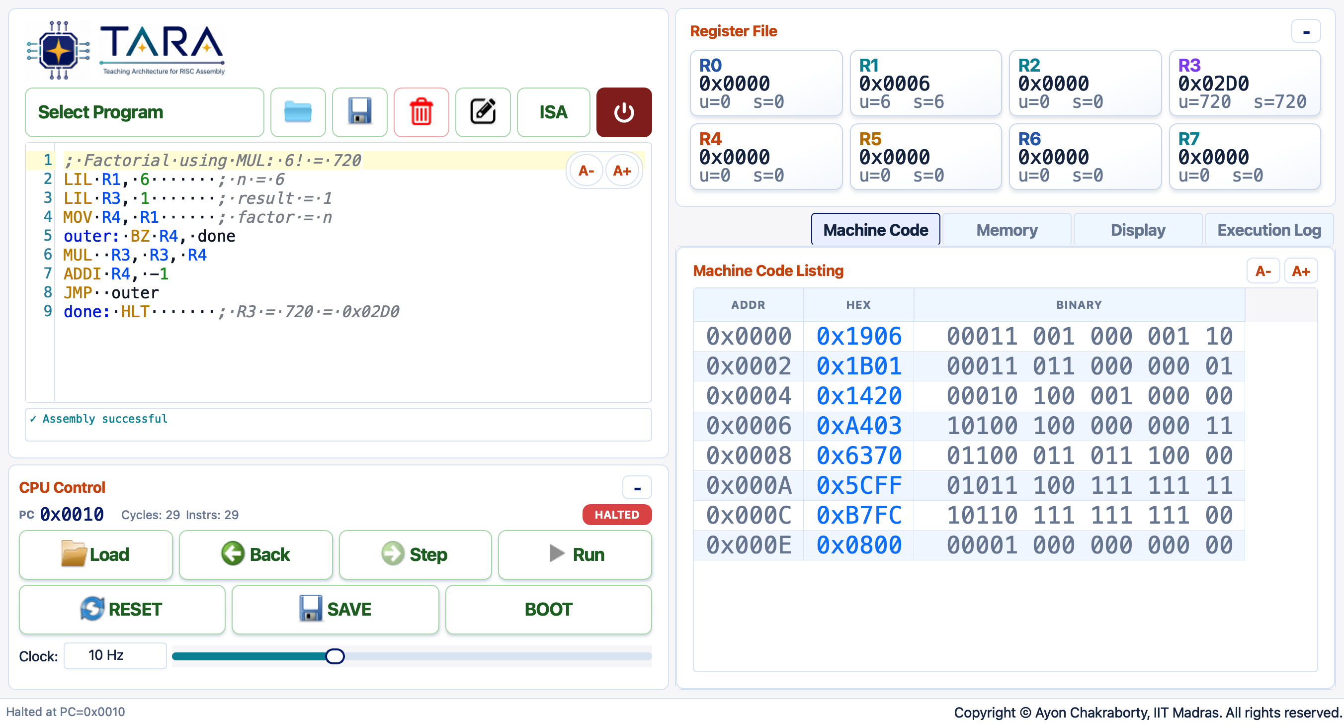
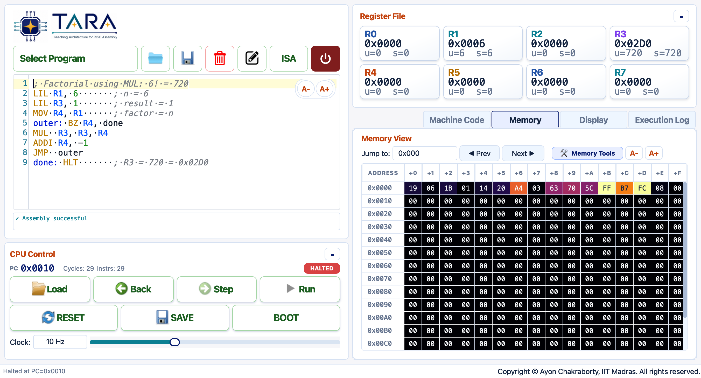
0x02D0 = 720. The HALTED badge appears in the CPU Control panel.Interface Tour
TARA Studio opens with two tabs across the top of the window: TARA CPU Simulator (the software CPU, described in this section) and TARA FPGA Tool (covered under TARA on Real Hardware). Everything below describes the TARA CPU Simulator tab.
Within that tab the view is divided into two panes. The left pane holds the Assembly Editor and CPU Control bar. The right pane shows the Register File and a tab bar with four views: Machine Code, Memory, Display, and Execution Log.
The full interface mid-execution of the factorial example — Machine Code listing highlighted at the current PC, registers updating on the right.
Assembly Editor
Line-numbered editor with syntax highlighting. Use the Select Program dropdown to load a bundled example, Open to load a file from disk, or ISA to open the full instruction reference.
Assembler errors appear below the editor with line numbers highlighted.
Machine Code Listing
After loading, each assembled instruction is shown with its address, hex encoding, binary fields, mnemonic, and operands. The row matching the current PC is highlighted in real time.
Register File
Eight live register cards showing the current value in hex, unsigned decimal, and signed decimal. Registers that changed in the last step are highlighted in blue.
Tab Panels
| Tab | Contents |
|---|---|
| Machine Code | Assembled instruction listing with live PC highlighting and binary field breakdown. |
| Memory | 256-byte memory browser with inline editing, heatmap coloring, and data tools (random fill, CSV import/export). |
| Display | Pixel display canvas mapped to a region of memory, for graphical output programs. |
| Execution Log | Per-instruction trace showing cycle, PC, mnemonic, operands, and register changes. |
Editor Toolbar
The toolbar sits directly below the TARA logo in the left pane. It contains the Select Program dropdown followed by five icon buttons and the red power button.

The editor toolbar — from left to right: Select Program dropdown, Open, Save, Delete, Rename, ISA, Power.
Select Program Dropdown
The green dropdown lists every bundled example program, organised by category (Basic, Intermediate, Advanced, Display, Games). Selecting an entry loads that program's source code into the editor and clears any unsaved work. Choose New File… (the first item) to start a blank program.

File Management Buttons
| Button | Name | What it does |
|---|---|---|
 |
Open | Open a .tara or .asm file from disk. The file is loaded into the editor and added to the Select Program dropdown so you can come back to it later. |
 |
Save | Save the current editor contents. If the program was opened from a file, it overwrites that file. If it is a new unsaved program, a Save As dialog appears to let you choose a filename. |
 |
Delete | Permanently delete the current program from disk and remove it from the dropdown. A confirmation prompt appears first. Built-in bundled examples cannot be deleted. |
 |
Rename | Rename the current program. A dialog asks for the new name; the file is renamed on disk and the dropdown entry is updated immediately. |
ISA & Power
| Button | Name | What it does |
|---|---|---|
 |
ISA | Opens the full TARA instruction set reference in a separate dialog — all instruction formats, mnemonics, field encodings, and pseudocode effects in one scrollable sheet. |
 |
Power | Exits the simulator. If the program has been run, a prompt offers to save the machine state before quitting. |
CPU Controls
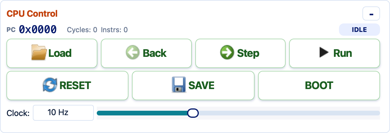
The CPU Control panel handles assembly, stepping, continuous execution, reset, save/boot, and clock-speed selection.
| Button | Action |
|---|---|
| Load | Assemble the editor text and write instruction words into memory starting at 0x0000. Existing data memory outside the code region is preserved. |
| Step | Execute one instruction. Updates all panels immediately. |
| Back | Undo the last step (up to 30 steps back). |
| Run / Stop | Run continuously at the selected clock speed. Click again (shown as Stop) to pause. |
| Reset | Clear the CPU state, re-assemble the current program, and clear the execution log. |
| Save | Save a full machine snapshot (source, registers, PC, memory, counters) to a JSON file. |
| Boot | Restore a previously saved machine-state JSON file. |
| FPGA ▶ | Assemble the current program and run it through the TARA FPGA Tool. If the tool is connected to FPGA USB, the program runs on the board; if it is connected to Simulator Memory, it runs on the local simulated CPU through the same memory-tool workflow. See Running a program from the Simulator tab. |
Clock Speed
Use the preset buttons (1 Hz, 100 Hz, 1 kHz, Max),
drag the slider, or type a custom value such as 2.5 Hz or 12 kHz.
Clock changes take effect immediately while the CPU is running.
At high speeds the simulator batches many instructions per timer tick; panel updates are
deferred until the program halts or you click Stop.
Writing Assembly
Syntax Rules
- Comments start with
;. - Labels end with
:, e.g.loop:. - Registers are
R0–R7(case-insensitive). - Immediates may be decimal (
6), hex (0x400), or binary (0b1010). - Memory operands use
offset(Rbase)syntax, e.g.0(R0),2(R4),-1(R2).
Branching and Labels
Write a label as the target of BZ, BN, JMP, or CALL.
The assembler converts it to a signed PC-relative instruction offset.
LIL R1, 5
loop: BZ R1, done
ADDI R1, -1
JMP loop
done: HLT
Building 16-bit Constants
LIL Rd, imm8 loads the low byte and clears the high byte.
LIH Rd, imm8 sets the high byte without disturbing the low byte.
Use them together to build any 16-bit constant or pointer.
; R0 = 0x0400  (base address of data array)
LIL R0, 0x00
LIH R0, 0x04
Register Conventions
| Register | Role |
|---|---|
R0–R5 | General purpose. |
R6 | Link register — CALL saves the return address here; RET reads it. |
R7 | Stack pointer — PUSH decrements it; POP increments it. Initialize before use. |
Instruction Set
All instructions are one 16-bit word. The assembler opcode occupies the top 5 bits; the layout of the remaining 11 bits depends on the format.
Instruction Formats
| Format | Instructions | Field Layout (bits 15–0) |
|---|---|---|
| F0 | NOP, HLT, RET | op[4:0] 00000000000 |
| F1 | ADD, SUB, MUL, AND, OR, XOR, SLT | op rd rsA rsB 00 |
| F2 | MOV, NOT | op rd rs 00000 |
| F3 | LIL, LIH, ADDI, SHL, SHR | op rd imm8 |
| F4 | LDW, STW, LDB, STB | op rdata rbase off5 |
| F5 | BZ, BN | op rtest rel8 |
| F6 | JMP, CALL | op rel11 |
| F7 | PUSH, POP | op rstk 00000000 |
Instruction Reference
| Group | Syntax | Effect |
|---|---|---|
| System | NOP | No operation. |
| System | HLT | Halt. PC advances by 2 before stopping. |
| Move | MOV Rd, Rs | Rd = Rs |
| Immediate | LIL Rd, imm8 | Rd = zero_extend(imm8) (clears high byte) |
| Immediate | LIH Rd, imm8 | Set Rd[15:8] = imm8, preserve Rd[7:0] |
| Memory | LDW Rd, off5(Rb) | Load 16-bit word from address Rb + sign_extend(off5) |
| Memory | STW Rs, off5(Rb) | Store 16-bit word at address Rb + sign_extend(off5) |
| Memory | LDB Rd, off5(Rb) | Load one byte (zero-extended) from memory |
| Memory | STB Rs, off5(Rb) | Store the low byte of Rs |
| Arithmetic | ADD Rd, Ra, Rb | Rd = Ra + Rb (wraps to 16 bits) |
| Arithmetic | SUB Rd, Ra, Rb | Rd = Ra - Rb |
| Arithmetic | ADDI Rd, imm8 | Rd = Rd + sign_extend(imm8) |
| Arithmetic | MUL Rd, Ra, Rb | Rd = Ra × Rb (low 16 bits) |
| Logic | AND/OR/XOR Rd, Ra, Rb | Bitwise operations |
| Logic | NOT Rd, Rs | Rd = ~Rs (16-bit) |
| Shift | SHL Rd, shamt | Logical left shift of Rd by shamt |
| Shift | SHR Rd, shamt | Logical right shift of Rd by shamt |
| Compare | SLT Rd, Ra, Rb | Rd = 1 if signed Ra < Rb, else 0 |
| Branch | BZ Rt, label | Branch if signed Rt == 0 |
| Branch | BN Rt, label | Branch if signed Rt < 0 |
| Jump | JMP label | Unconditional PC-relative jump |
| Call | CALL label | Save return address in R6, then jump |
| Call | RET | Set PC from R6 |
| Stack | PUSH Rs | R7 -= 2, then store word at Mem[R7] |
| Stack | POP Rd | Load word from Mem[R7], then R7 += 2 |
ADDI sign-extends its 8-bit immediate.
Memory offsets (off5) are 5-bit signed values.
BZ/BN treat the test register as signed.
SLT compares signed 16-bit values.
Memory Layout
TARA has a flat, byte-addressed address space of exactly 2 048 bytes
(2 KB), at addresses 0x0000–0x07FF.
There is no cache, no virtual memory, and no hardware memory protection —
every byte is directly readable and writable by any instruction.
The table below describes the conventional use of each region:
The assembler loads instructions here starting at 0x0000. Up to 512 words (1 024 bytes) of machine code fit in this region. Temporary values can share space if the program is short.
Game state variables, sort / search arrays, glyph sprite assets, and bit-mask lookup tables. Game programs set R7 = 0x0410 as a frame-pointer and access every variable via a signed word offset.
Grows downward. Set R7 = 0x05F0 before the first PUSH or CALL. The low end of this range also doubles as a pre-seeded data table (food positions, pipe gaps, obstacle sequences) for game programs.
0x05FF — Keyboard register: the simulator writes live arrow-key bits here while the Display canvas has focus (bit 0 UP · 1 DOWN · 2 LEFT · 3 RIGHT · 4 QUIT). Remaining addresses reserved for future peripherals.
64×64 pixels, 1 bit/pixel, 8 pixels per byte, MSB = leftmost pixel. Row 0 is the bottom of the canvas. Pixel (x, y): byte = 0x0600 + y×8 + x÷8, bit = 7 − (x mod 8). Any write here appears on the Display tab immediately.
Suggested Address Conventions
| Address | Typical use |
|---|---|
0x0000 | Entry point — assembler always starts loading here |
0x0400 | Start of general-purpose data (arrays, sort buffers) |
0x0410 | Base for game state variables (use R7 = 0x0410 with signed offsets) |
0x0420 | Bit-mask lookup table for single-pixel drawing (8 bytes) |
0x0440 | Snake body ring buffer / secondary data area |
0x0500 | Food queue, pipe-gap table, or obstacle data |
0x05F0 | Initial stack pointer — set R7 = 0x05F0 before any CALL |
0x05FF | Keyboard register (read only; written by the simulator) |
0x0600 | Display framebuffer base |
0x0600.
Memory Tools
TARA has 2048 bytes of byte-addressed memory (0x000–0x7FF).
The assembler loads instructions at 0x0000; data and the stack live in higher
addresses by convention.
Suggested Memory Map
| Range | Typical Use |
|---|---|
0x000–0x3FF | Program code (assembler loads here) |
0x400–0x4FF | Data arrays and output buffers |
0x500–0x5FF | Stack (initialize R7 to 0x500 or higher) |
0x600–0x7FF | Scratch / experiments |
Memory Viewer
The Memory tab shows 256 bytes at a time (16 rows × 16 columns).
Use Jump to (e.g. 0x400) to navigate, or click
Prev / Next to page through. Click any byte cell to
edit it inline — use 0x or 0b prefixes for clarity.
The Hex / Dec radio buttons in the toolbar switch every byte cell
between hexadecimal and decimal display.
The Memory tab with the heatmap colormap enabled — byte values are color-coded, making patterns like instruction encoding visible at a glance.
Memory Tools
| Tool | What It Does |
|---|---|
| Random Fill | Writes random bytes or words at a given address range. Useful for generating test arrays for sorting and searching programs. |
| CSV Import | Reads rows of address, hex, decimal and writes them into memory. Accepts an optional header row. |
| CSV Export | Writes a selected memory range to a CSV file. Zero bytes can be included or excluded. Default path: local/config/memory/memory_dump.csv. |
CSV Format
address,hex,decimal
0x0400,05,5
0x0401,03,3
0x0402,01,1
Display Output Advanced
The Display tab renders a 64×64-pixel, 1-bit canvas
that is memory-mapped to the top 512 bytes of TARA's address space.
Any byte your program writes to 0x0600–0x07FF is reflected
on the canvas in real time. Each byte encodes 8 horizontal pixels, with the
most-significant bit being the leftmost pixel of that group. The default
palette is Classic Amber: bit 0 is Deep
Charcoal #1C1C1C, and bit 1 is Amber Glow
#FFB000.
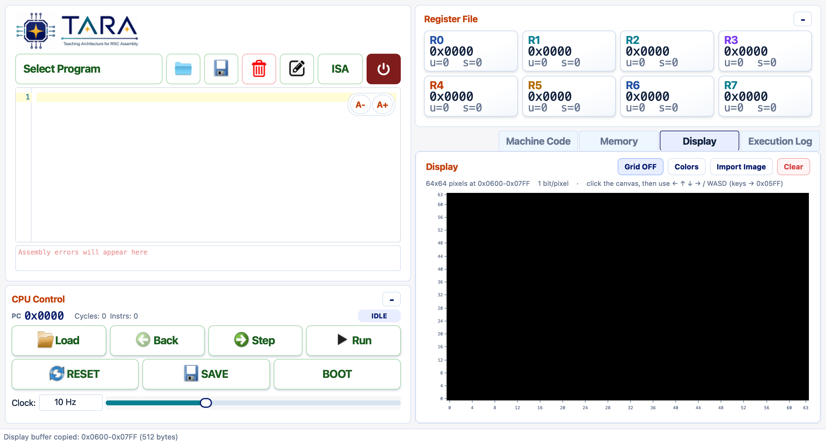
The Display tab with a blank 64×64 canvas. The toolbar controls the grid overlay, palette colors, image import, and clearing.
Memory Map
| Address range | Contents |
|---|---|
0x0600–0x07FF | Framebuffer — 512 bytes, 64×64 pixels, 1 bit/pixel |
0x05FF | Keyboard register — live one-hot key bits (see Keyboard Input) |
Row 0 is the bottom row of the canvas; row 63 is the top. The row stride is 8 bytes. Pixel (x, y) lives in byte 0x0600 + y × 8 + x ÷ 8, bit position 7 − (x mod 8).
Display Controls
| Button | Action |
|---|---|
| Grid OFF / ON | Toggle a pixel grid overlay on top of the canvas. |
| Colors | Set the two palette colors — color for bit value 0 (background) and bit value 1 (foreground). |
| Import Image | Scale and dither a PNG/JPG/GIF into display memory or store it as a portable glyph asset. |
| Clear | Zero the entire framebuffer (all pixels off). |
Importing an Image
Click Import Image and pick any PNG, JPG, or GIF.
An Import Image dialog lets you choose the size and destination.
Below, local/config/images/gameover.jpg (640×360) is imported
at 64×64 pixels directly into the framebuffer.
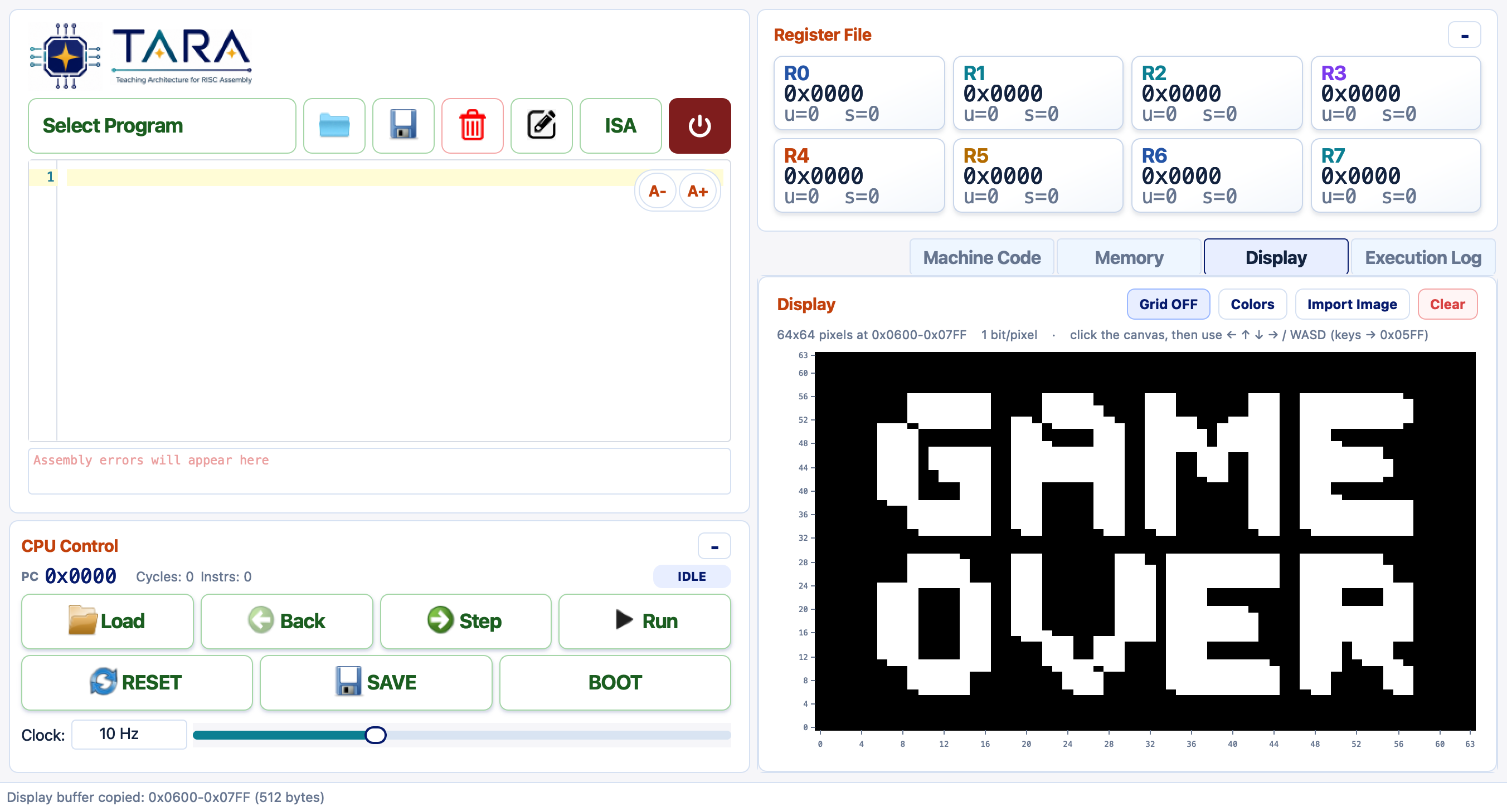
gameover.jpg imported at 64×64 — the full-screen pixel art appears on the canvas immediately after clicking OK.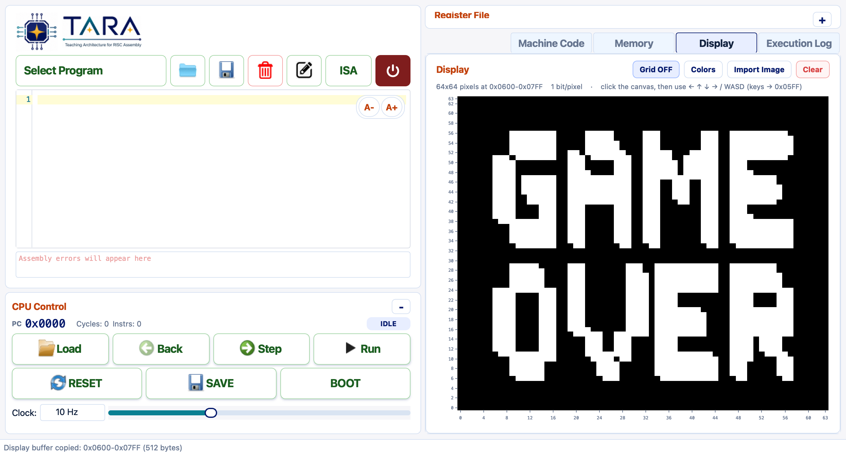
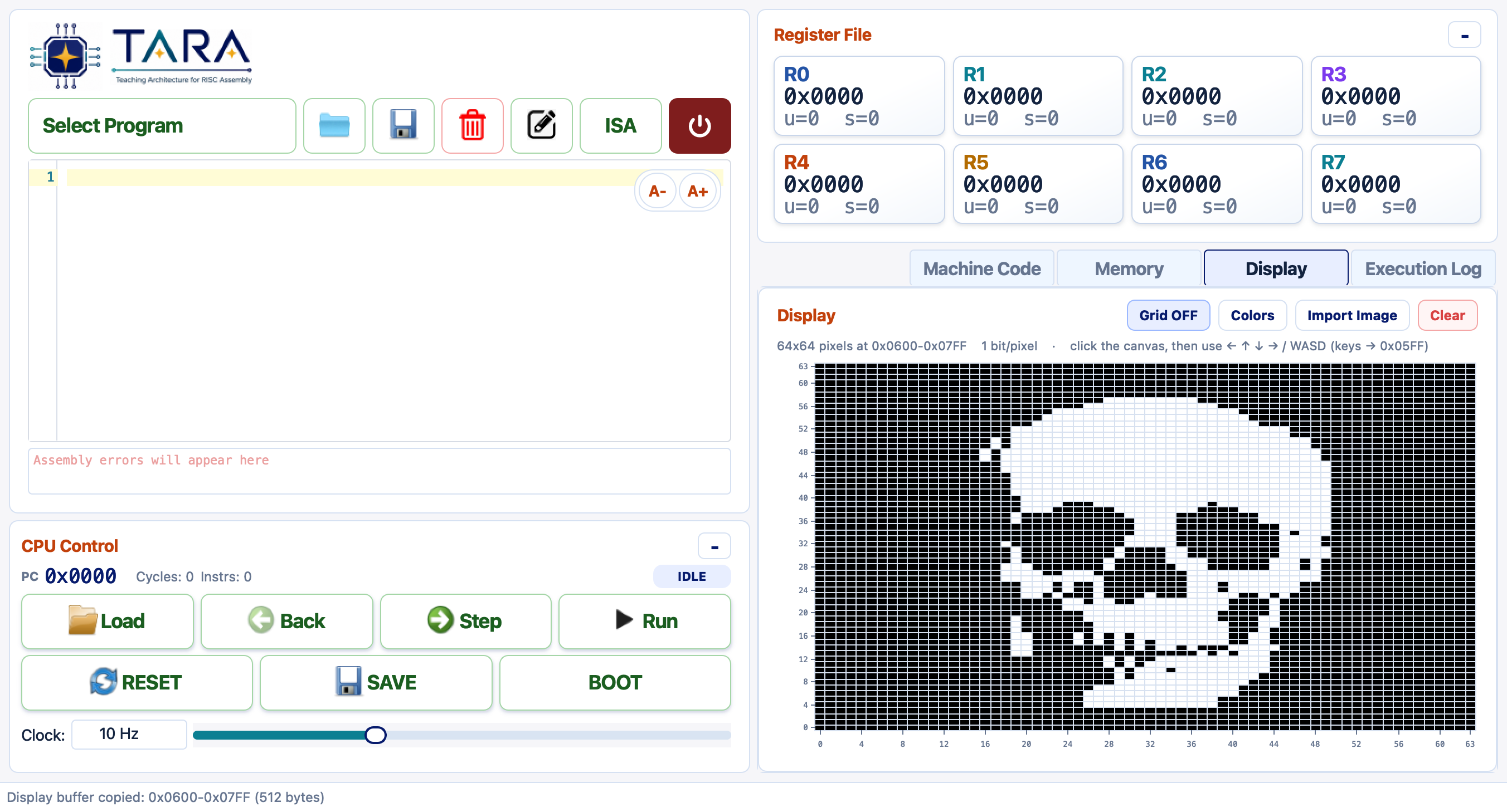
skull.png image at 64×64 with Grid ON. Each cell is one pixel — useful for locating exact bit positions while writing display routines.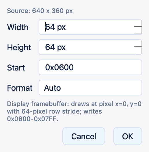
gameover.jpg. Width and Height are set to 64; Format Auto detects that Start 0x0600 is inside the framebuffer range and writes all 512 bytes directly.Import Dialog Options
| Field | Meaning |
|---|---|
| Width / Height | Scale the image to this size in pixels before dithering. Values independent of 64 are allowed — useful for small glyph sprites. |
| Start address | Destination byte address. Must fit within 0x0000–0x07FF. |
| Format — Auto | If Start is inside 0x0600–0x07FF the image is written as a framebuffer; otherwise it is stored as a glyph asset. |
| Format — Display framebuffer | Writes the full 512-byte framebuffer. Pixels appear on the canvas immediately. Origin is bottom-left to match TARA's row convention. |
| Format — Glyph asset | Stores the scaled image at any address using the compact glyph format (see below). Does not affect the live display until code blits it into the framebuffer. |
Glyph Asset Format
A glyph asset is a self-describing sprite that can live anywhere in data memory. It is completely independent of the display size. The layout is:
base+0    width  (1 byte)
base+1    height (1 byte)
base+2…   packed pixel rows — ceil(width/8) bytes per row, top row first
           MSB of each byte = leftmost pixel of that group
For a 16×16 glyph the payload is 2 + ceil(16/8) × 16 = 34 bytes.
The memory view below shows the skull glyph written to 0x0400:
bytes 0x0400 = 16 (width) and 0x0401 = 16 (height),
followed by 32 bytes of packed pixel data.
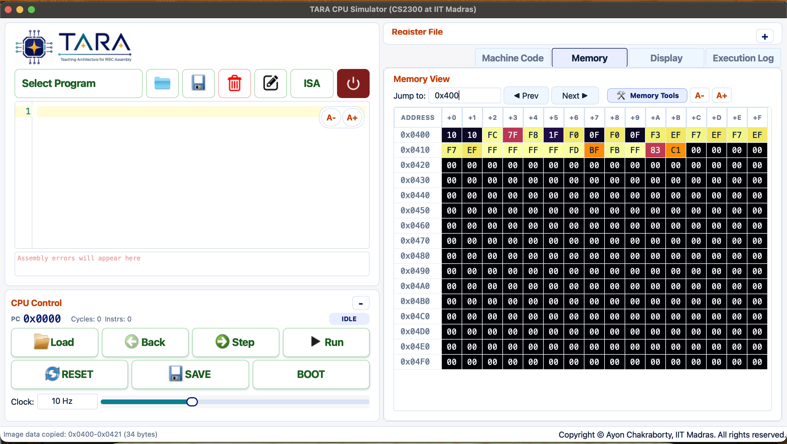
Memory tab with heatmap enabled, scrolled to 0x0400. The non-zero bytes at 0x0400–0x0421 are the 34-byte skull glyph (width=16, height=16, then 32 packed pixel bytes). The heatmap colour makes the glyph footprint immediately visible.
Bouncing Ball with a Custom Glyph
The Display Bouncing Ball example ships with a built-in 16×16 circular ball,
but it is designed to use whatever glyph is stored at 0x0400.
On startup the program reads Mem[0x0400] (the width byte); if it is non-zero
the existing glyph is used; if it is zero the program writes its own default ball there.
This means you can substitute any 1-bit sprite simply by pre-loading it before clicking Load.
- Click Import Image and select any image (e.g.
local/config/images/skull.pngorgameover.jpg). - Set Width =
16, Height =16, Start =0x0400, Format = Glyph asset. Click OK. - Select Display Bouncing Ball from the Select Program dropdown and click Load.
- Switch to the Display tab, collapse the Register File with − for a full-size view, then click Run.
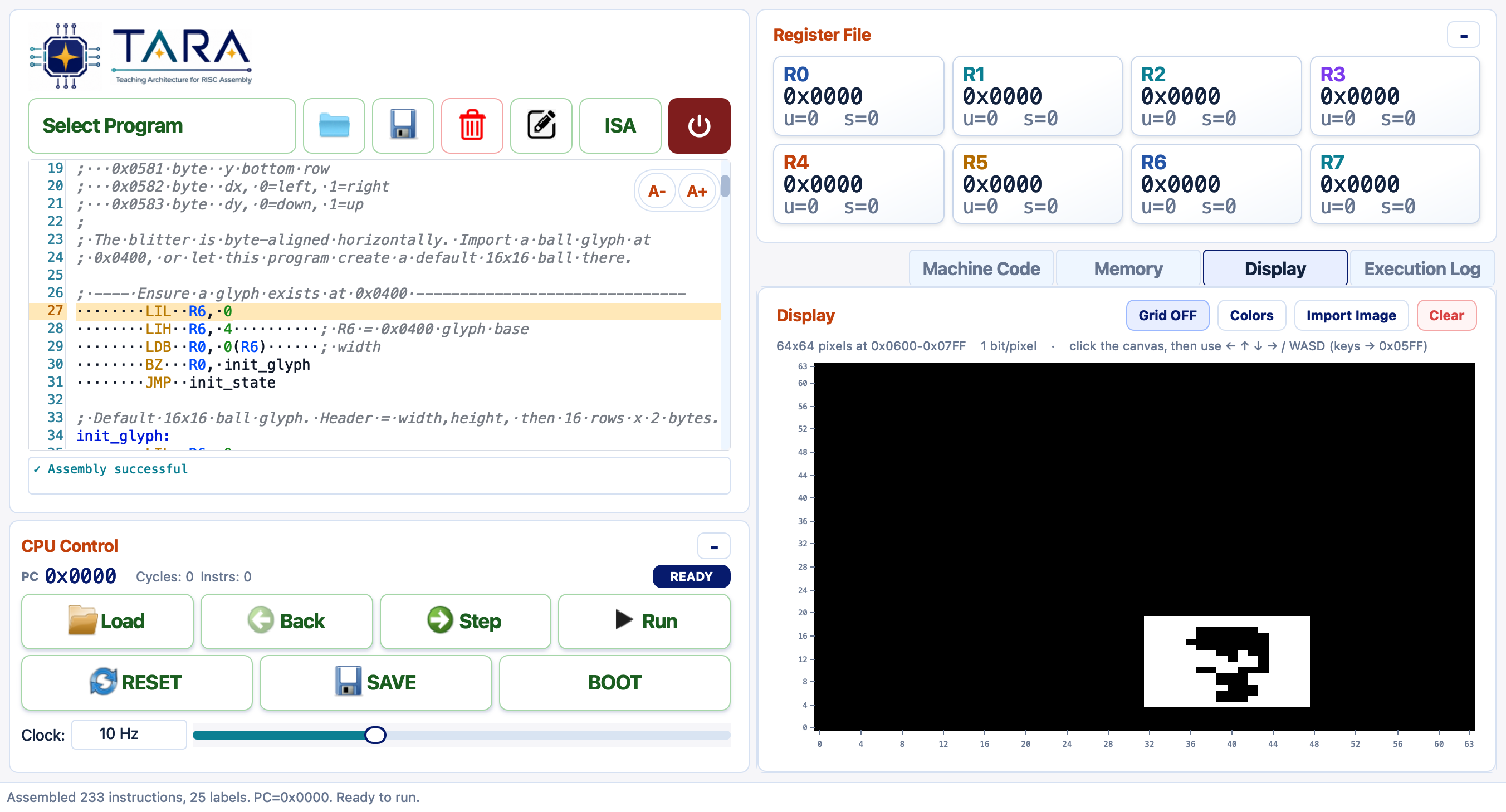
The Display Bouncing Ball program running with the 16×16 skull glyph pre-loaded at 0x0400. The skull bounces around the 64×64 canvas, reversing direction at each wall — the Register File is visible on the right so you can track animation-state variables in memory.
How the Blit Works
The bouncing-ball program draws each frame by copying glyph rows into the framebuffer byte by byte. If a glyph asset uses the opposite bit convention from the framebuffer palette, invert each byte with NOT before writing:
; Draw one glyph row into the framebuffer
draw_byte:
    LDB  R0, 0(R7)   ; load packed glyph byte  (1 = sprite pixel)
    NOT  R0, R0      ; invert if the glyph uses the opposite convention
    STB  R0, 0(R6)   ; store to framebuffer row pointer
    ADDI R7, 1
    ADDI R6, 1
    ADDI R3, -1
    JMP  draw_byte
The erase pass before each move clears only the rows the glyph occupied,
avoiding full-framebuffer redraws and preventing flicker.
Animation state (x byte-column, y bottom row, dx, dy) is kept at
0x0580–0x0583 so it survives between frames without using registers.
Storing a Glyph Outside the Framebuffer
Any address below 0x0600 is safe for glyph storage as long as it does not
overlap your program code or data. Conventional slots:
| Address | Typical use | Bytes for 16×16 |
|---|---|---|
0x0400 | Primary sprite / ball glyph (used by the bouncing-ball example) | 34 |
0x0430 | Second sprite, or large glyph overflow | 34 |
0x0500 | Larger glyph (e.g. 32×32 = 130 bytes) or alternate sprite | 130 |
Keyboard Input Advanced
TARA has a single memory-mapped keyboard register at
0x05FF (the byte just below the framebuffer). While the
Display canvas has focus, the simulator continuously writes the
currently-held control keys into this byte as one-hot bits. A program
reads them with a single LDB and tests the bit it cares about — this
is how interactive examples like Snake and Ping Pong
are steered.
Bit Layout (read from 0x05FF)
| Bit | Mask | Keys | Meaning |
|---|---|---|---|
| 0 | 0x01 | ↑ / W | UP — move toward the top of the screen |
| 1 | 0x02 | ↓ / S | DOWN — move toward the bottom |
| 2 | 0x04 | ← / A | LEFT |
| 3 | 0x08 | → / D | RIGHT |
| 4 | 0x10 | Q | QUIT — a convention games use to halt |
The bits are level / held, not edge-triggered: a bit stays
1 for as long as the key is down and returns to 0 when
released. Several keys held at once combine (e.g. ↑+→ reads as
0x09). Bits 5–7 are unused and always read 0.
Because framebuffer row 0 is the bottom of the screen,
UP moves an object toward higher y and
DOWN toward lower y.
Using It in the App
- Open the Display tab and click the canvas once so it has keyboard focus.
- Click Run (a clock of ~300–2000 Hz feels responsive).
- Steer with the arrow keys or W/A/S/D.
Reading the Keyboard in Assembly
Load the register, then isolate a bit with AND and branch on the result.
BZ is taken when the bit is clear (key not held):
; --- poll the keyboard once per frame ---
    LIL  R0, 0xFF
    LIH  R0, 0x05        ; R0 = 0x05FF (keyboard register)
    LDB  R1, 0(R0)       ; R1 = live key bits

    LIL  R2, 4
    AND  R2, R1, R2      ; isolate LEFT  (bit 2 = 0x04)
    BZ   R2, not_left    ; bit clear -> key is up, skip
    ; ... LEFT is held: move the player left ...
not_left:

    LIL  R2, 8
    AND  R2, R1, R2      ; isolate RIGHT (bit 3 = 0x08)
    BZ   R2, not_right
    ; ... RIGHT is held: move the player right ...
not_right:

    LIL  R2, 16
    AND  R2, R1, R2      ; isolate QUIT  (bit 4 = 0x10)
    BZ   R2, no_quit
    HLT                  ; Q held -> stop
no_quit:Writing Games for TARA Advanced
TARA ships with four fully playable games: Snake,
Ping Pong, Flappy Bird, and Racing.
They run on the 64×64-pixel display, read
live arrow-key input from the keyboard register at 0x05FF, and
fit entirely within the 1 KB code region below 0x0400.
They are the best worked examples of display, real-time, and interactive
programming on the TARA ISA — and a practical guide to writing your own game.
Flappybirds
A fixed-position bird must stay above scrolling vertical mountains. The
mountain heights are hardcoded in memory at 0x0500 and cycle
through a wrap marker, making it a compact example of keyboard input,
display drawing, data tables, and collision tests.
How to play:
- Select Flappybirds from the dropdown, click Load.
- Open the Display tab and click the canvas.
- Set the clock to ~1 kHz and click Run.
- Tap or hold ↑ / W to jump. Avoid touching the pipe edges, floor, or ceiling. Q quits.
Gameplay Clips
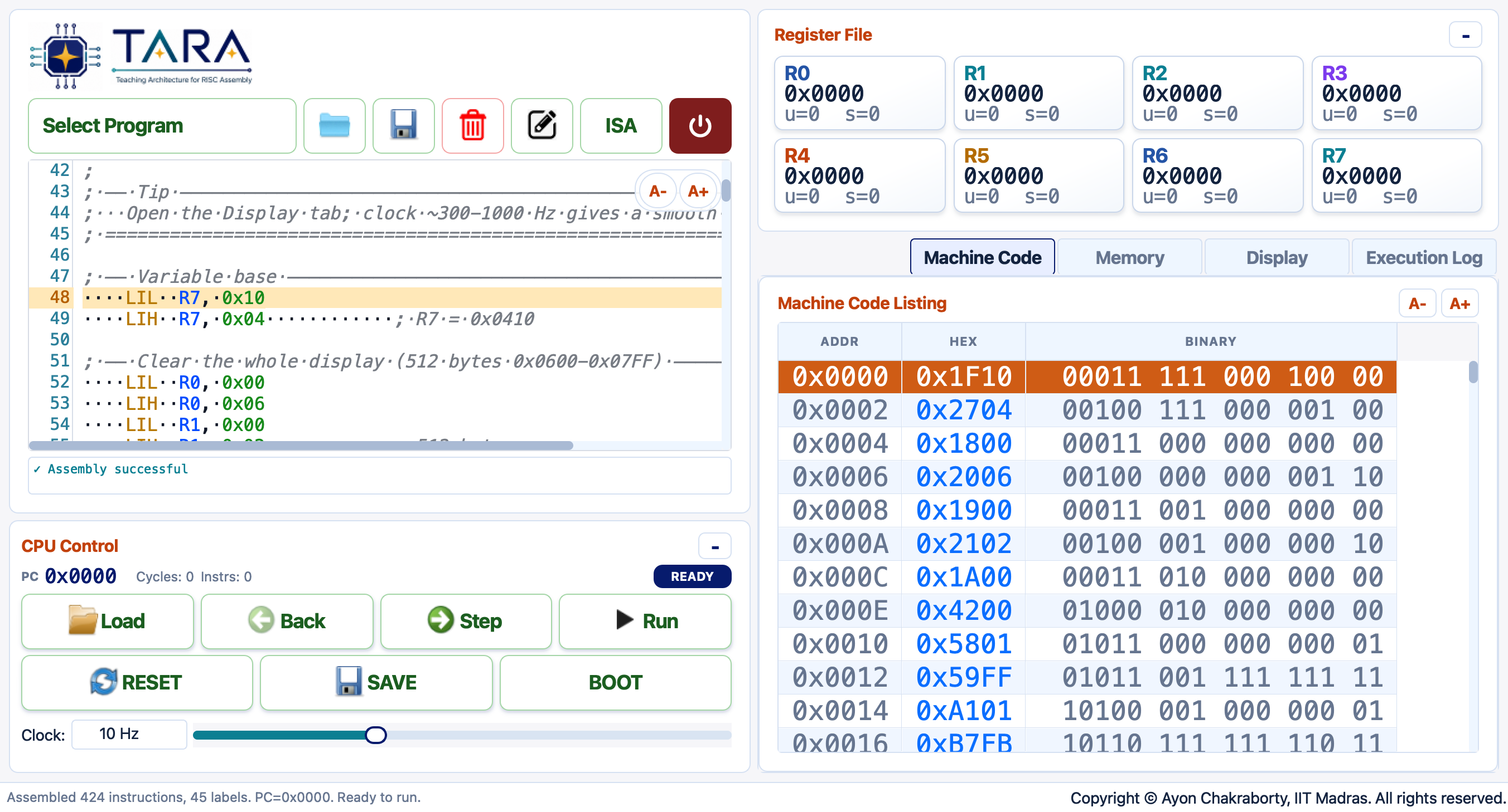
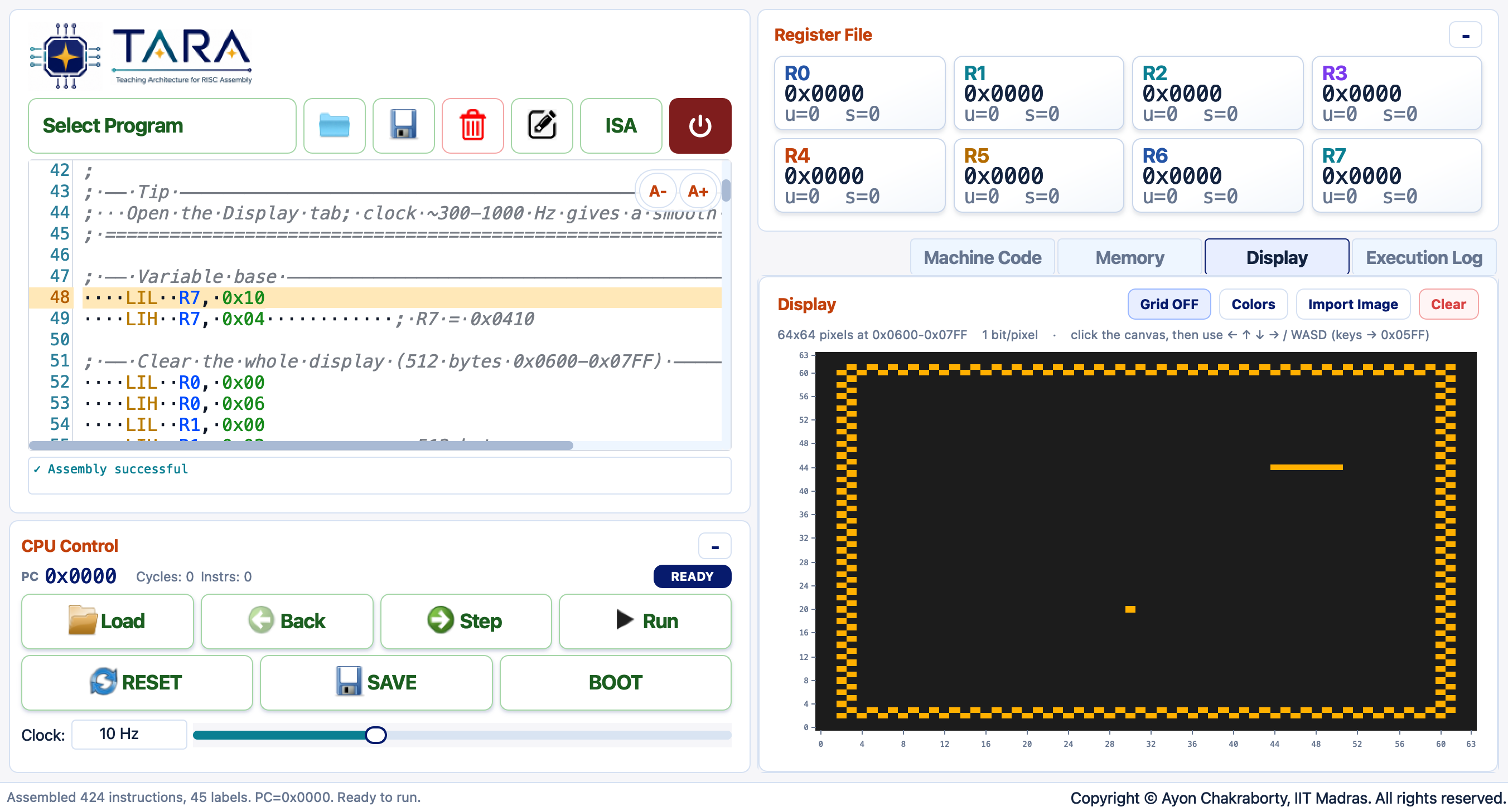
These short recordings show the 64×64 Display canvas during play. Snake, Racing, and Ping Pong are captured tightly around the display area, so they are shown side by side for quick comparison.
Snake
A 1-pixel-wide snake moves through the arena eating food pixels and growing longer. Hitting the boundary wall or biting its own body ends the game.
How to play:
- Select Snake from the Select Program dropdown, click Load.
- Open the Display tab and click the canvas to give it focus.
- Set the clock to ~1 kHz and click Run.
- Steer with ← → ↑ ↓ (or WASD). Q quits.
Racing
A top-down lane-avoidance game. Two opponent cars scroll downward on a two-lane road; steer your car left or right to dodge them. The road background is drawn once at startup, and opponents are redrawn by updating only the two rows they vacate and the two new rows they occupy — giving smooth scrolling at low clock speeds.
How to play:
- Select Racing from the dropdown, click Load.
- Open the Display tab and click the canvas.
- Set the clock to ~1–2 kHz and click Run.
- Change lane with ← / → (or A / D). Q quits.
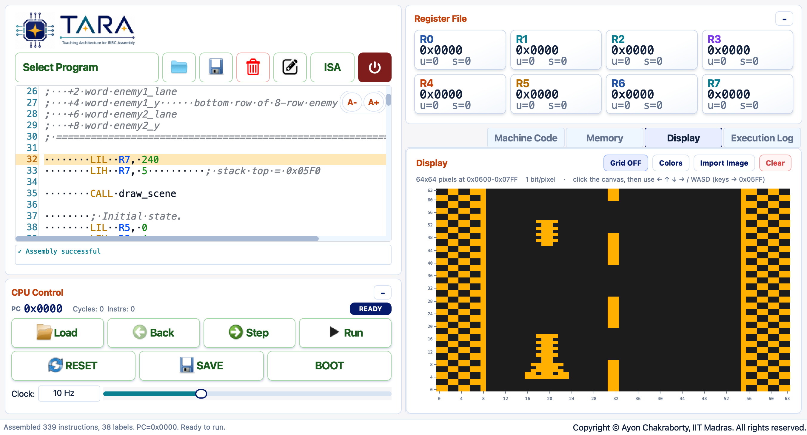
Racing in action — the two-lane road scrolls upward. Opponent cars descend from the top; steer left or right to dodge them before they reach the player's position at the bottom.
Ping Pong
A 2×2-pixel ball bounces off the top, left, and right walls. The bottom is open and defended by a 12-pixel-wide horizontal bat that you slide left and right. Miss the ball and the game ends.
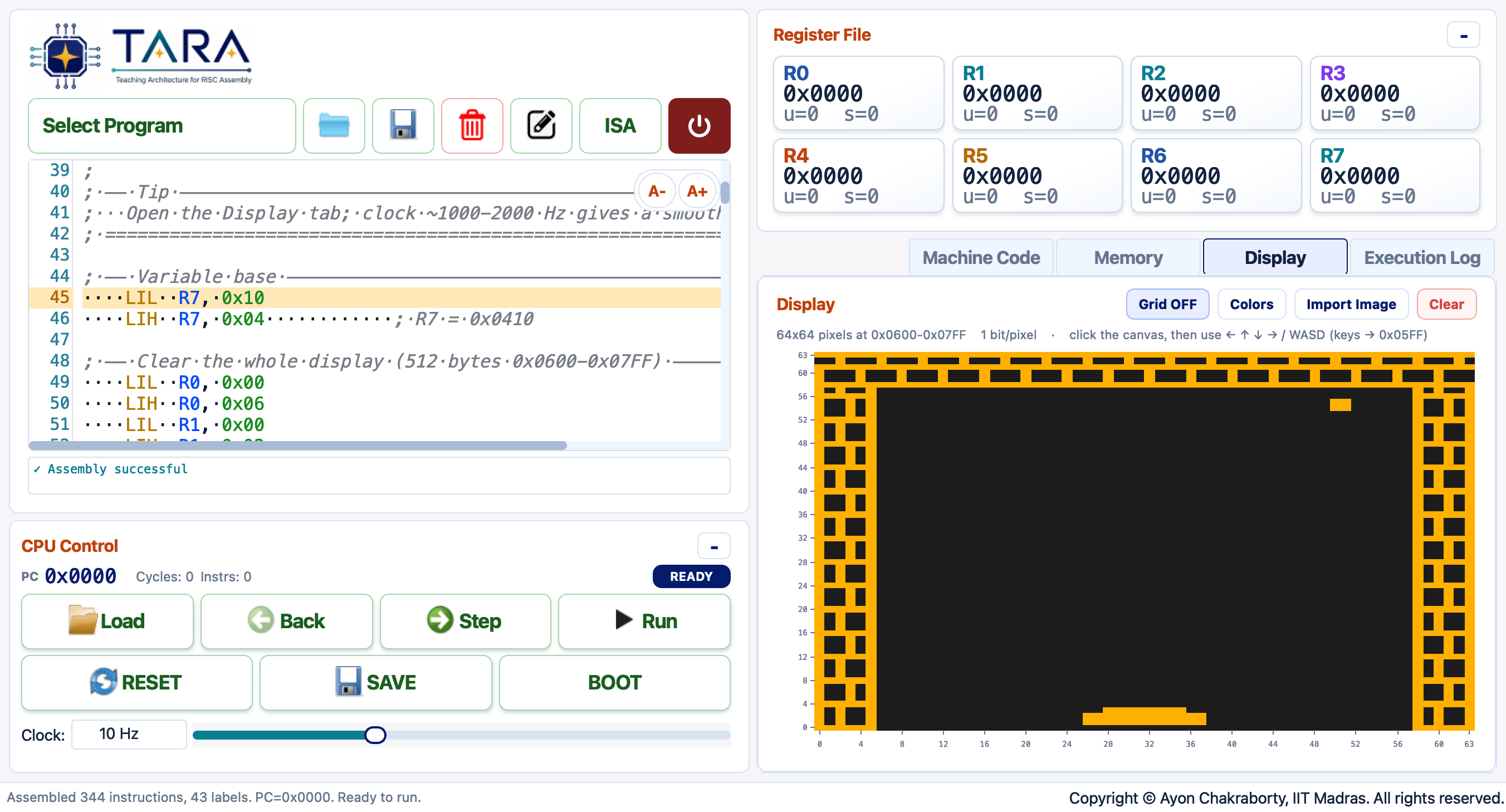
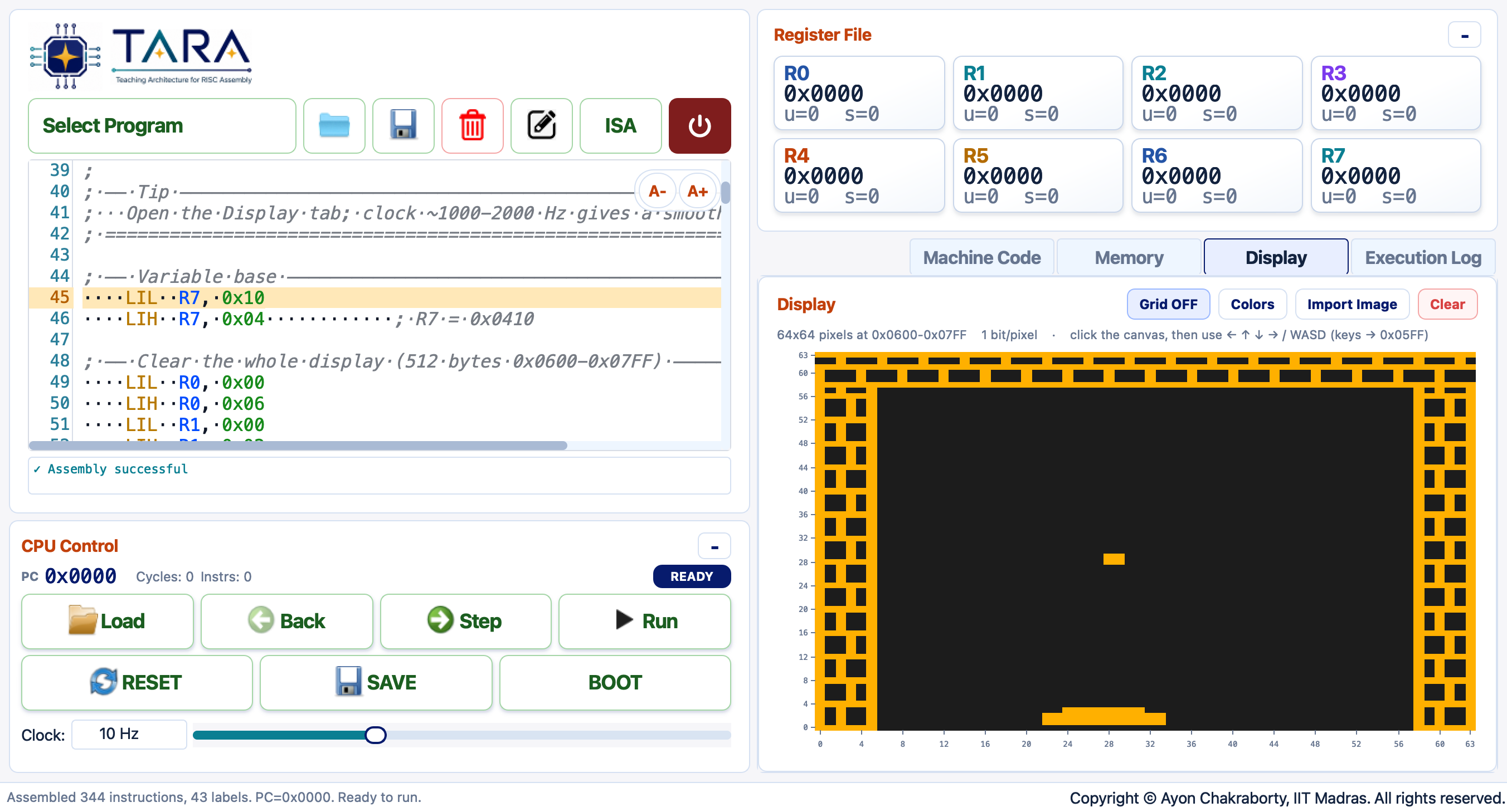
How to play:
- Select Ping Pong from the dropdown, click Load.
- Open the Display tab and click the canvas.
- Set the clock to ~1–2 kHz and click Run.
- Slide the bat with ← / → (or A / D). Q quits.
✏️ Writing Your Own Game
The four bundled games all share the same structural patterns. Understanding those patterns is the key to writing new games — and to understanding the trade-offs that constrain every low-level graphics program.
1 · The Core Game Loop
Every TARA game is an infinite loop: read input → update state → redraw changed pixels → repeat. Static elements (walls, arena borders, background) are drawn once during initialisation and never touched again.
; ── Initialisation (runs once) ──────────────────────────────────────
init:
    ; 1a. Set the stack pointer so CALL / RET work
    LIL  R7, 0xF0
    LIH  R7, 0x05       ; R7 = 0x05F0  (stack grows down from here)

    ; 1b. Clear the framebuffer
    LIL  R0, 0x00
    LIH  R0, 0x06       ; R0 = 0x0600 (fb base)
    LIL  R1, 0x00
    LIH  R1, 0x02       ; R1 = 512    (loop counter)
    LIL  R2, 0
clr: STB  R2, 0(R0)
    ADDI R0, 1
    ADDI R1, -1
    BZ   R1, clr_done
    JMP  clr
clr_done:

    ; 1c. Draw static elements (walls, borders, score bar …)
    CALL draw_walls

    ; 1d. Set initial game state variables
    CALL init_state

    JMP  main_loop      ; enter the game loop

; ── Main game loop (repeats every frame) ────────────────────────────
main_loop:
    ; Step 1: Read keyboard
    LIL  R0, 0xFF
    LIH  R0, 0x05       ; R0 = 0x05FF
    LDB  R1, 0(R0)      ; R1 = live key bits

    ; Step 2: Update game state
    CALL update_player
    CALL update_enemies
    CALL check_collisions

    ; Step 3: Redraw only what changed
    CALL erase_old_positions
    CALL draw_new_positions

    ; Step 4: Optional software delay for pacing
    ; (alternatively just run at a low clock frequency)

    JMP  main_loop      ; loop forever

game_over:
    ; Draw a game-over message, then halt
    HLT
2 · Organising State Variables
All games use R7 as a frame-pointer into the data region and access variables via signed word offsets. This keeps every variable in exactly one place and makes subroutines straightforward.
; ── Setup: R7 = 0x0410 (variable base pointer) ─────────────────────
    LIL  R7, 0x10
    LIH  R7, 0x04       ; R7 = 0x0410

; ── Access pattern ──────────────────────────────────────────────────
; Variable layout (word offsets from R7):
;   -16  player_x        -14  player_y
;   -12  velocity_x      -10  velocity_y
;    -8  score             -6  lives
;    -4  enemy_x           -2  enemy_y
;     0  temp_x             2  temp_y
;     4  eat_flag           …  (add more as needed)

    LDW  R0, -16(R7)    ; load player_x
    ADDI R0, 1          ; x += 1
STW R0, -16(R7) ; store player_x3 · The Bit-Mask Lookup Table
TARA does not have a variable-shift instruction — SHL and SHR
only accept an immediate shift count. To set or clear a specific bit within a byte
(i.e. a single pixel) all games precompute the eight possible masks at startup:
; ── Write bit-mask table at 0x0420 ──────────────────────────────────
init_masks:
    LIL  R0, 0x20
    LIH  R0, 0x04       ; R0 = 0x0420 (table base)
    LIL  R1, 128        ; 0x80
    STB  R1, 0(R0)      ; masks[0] = 0x80  (leftmost pixel)
    LIL  R1, 64
    STB  R1, 1(R0)      ; masks[1] = 0x40
    LIL  R1, 32
    STB  R1, 2(R0)
    LIL  R1, 16
    STB  R1, 3(R0)
    LIL  R1, 8
    STB  R1, 4(R0)
    LIL  R1, 4
    STB  R1, 5(R0)
    LIL  R1, 2
    STB  R1, 6(R0)
    LIL  R1, 1
    STB  R1, 7(R0)      ; masks[7] = 0x01  (rightmost pixel)
    RET
4 · Single-Pixel Drawing (set_px / clr_px / test_px)
Three primitive subroutines underlie every display operation.
All three take R0 = x, R1 = y on entry and
destroy R2–R5:
; ── Compute byte address and mask into R2 / R5 ──────────────────────
; (shared preamble used by set, clr, and test)
px_addr:
    MOV  R2, R1         ; y
    SHL  R2, 3          ; y * 8  (row stride)
    MOV  R3, R0
    SHR  R3, 3          ; x / 8  (byte column)
    ADD  R2, R2, R3
    LIL  R3, 0x00
    LIH  R3, 0x06
    ADD  R2, R2, R3     ; R2 = 0x0600 + y*8 + x/8  (byte address)
    LIL  R4, 7
    AND  R3, R0, R4     ; R3 = x & 7
    LIL  R4, 0x20
    LIH  R4, 0x04       ; R4 = 0x0420 (mask table base)
    ADD  R4, R4, R3
    LDB  R5, 0(R4)      ; R5 = mask for bit position
    RET

; ── SET pixel (x, y) → turn it ON ───────────────────────────────────
set_px:
    CALL px_addr
    LDB  R3, 0(R2)
    OR   R3, R3, R5
    STB  R3, 0(R2)
    RET

; ── CLEAR pixel (x, y) → turn it OFF ────────────────────────────────
clr_px:
    CALL px_addr
    LDB  R3, 0(R2)
    NOT  R5, R5         ; invert mask: 0 bit at target position
    AND  R3, R3, R5
    STB  R3, 0(R2)
    RET

; ── TEST pixel (x, y) → R2 = non-zero if lit, 0 if dark ─────────────
test_px:
    CALL px_addr
    LDB  R3, 0(R2)
    AND  R2, R3, R5     ; isolate the target bit
    RET
CALL saves the return address in R6 (the link register); RET
jumps to R6. If one subroutine calls another, the outer call's return
address is overwritten. Use PUSH R6 / POP R6 around nested calls (R7 must
be initialised first), or structure subroutines so they are leaf functions that
do not call anything else.
5 · Flicker-Free Animation
The golden rule: draw the new position before erasing the old one. The display is never blank between frames, so the eye never sees a flash. For a moving single pixel the pattern is:
; ── Move one pixel object: draw new FIRST, erase old AFTER ──────────
    LDW  R0, 0(R7)      ; new_x
    LDW  R1, 2(R7)      ; new_y
    CALL set_px         ; pixel is NOW lit at the new position

    LDW  R0, -16(R7)    ; old_x
    LDW  R1, -14(R7)    ; old_y
    CALL clr_px         ; NOW safe to clear the old position

    ; save new coords as old
    LDW  R0, 0(R7)
    STW  R0, -16(R7)
    LDW  R0, 2(R7)
    STW  R0, -14(R7)
For wider objects (e.g. the 12-pixel bat in Ping Pong) only the leading and trailing columns need updating when the bat slides one pixel — the middle stays untouched. This cuts the cost of one bat move from 36 pixel operations to just 6.
6 · Collision Detection
TARA games use two different collision strategies depending on what needs to be checked.
Framebuffer collision (Snake, Ping Pong walls) — read the destination pixel before drawing there. A lit pixel is an occupied cell:
; ── Test destination before advancing ───────────────────────────────
    LDW  R0, 4(R7)      ; new_x
    LDW  R1, 6(R7)      ; new_y
    CALL test_px        ; R2 = 0 if clear, non-zero if occupied
    BZ   R2, safe       ; clear → move is legal
    JMP  game_over      ; occupied → collision
safe:
Arithmetic collision (Flappy Bird, Racing) — compare object coordinates directly. Faster and more precise for axis-aligned rectangles:
; ── Check if player x,y overlaps a rectangular obstacle ─────────────
;   player is a 4x2 block at (px, py); obstacle spans [ox, ox+w) × [oy, oy+h)
    LDW  R0, -16(R7)    ; player x
    LDW  R2, enemy_x    ; obstacle left
    LDW  R3, enemy_x
    ADDI R3, 6          ; obstacle right edge
    SLT  R4, R0, R2     ; player_x < obstacle_left ?
    BZ   R4, no_overlap ; ...
    SLT  R4, R3, R0     ; obstacle_right < player_x ?
    BZ   R4, no_overlap
    ; same check for y …
    JMP  game_over
no_overlap:
7 · Pre-seeded Data Tables
Games that need a sequence of random-looking values (food positions, pipe gaps,
obstacle heights) use a pre-seeded byte table starting at
0x0500. A pointer walks through the table; a sentinel byte
(0xFF) causes the pointer to wrap back to the start.
Edit the table before loading to change the level layout.
; ── Table in memory (written by program init or Import → CSV) ───────
; 0x0500:  30, 10,  50, 20,  35, 45,  0xFF  ; (x,y) pairs; 0xFF = wrap

; ── Reading the next entry ───────────────────────────────────────────
    LDW  R0, -2(R7)     ; food_ptr  (initialised to 0x0500)
    LDB  R1, 0(R0)      ; read x byte
    LIL  R2, 0xFF
    SUB  R3, R1, R2
    BZ   R3, wrap       ; 0xFF sentinel → wrap
    STW  R1, 0(R7)      ; food_x = table[ptr]
    LDB  R1, 1(R0)      ; read y byte
    STW  R1, 2(R7)      ; food_y
    ADDI R0, 2          ; ptr += 2
    STW  R0, -2(R7)     ; update food_ptr
    JMP  done_food
wrap:
    LIL  R0, 0x00
    LIH  R0, 0x05       ; reset ptr to 0x0500
    STW  R0, -2(R7)
    JMP  read_next      ; try again from the start
done_food:
8 · Choosing a Clock Frequency
The clock controls how many instructions execute per second, which determines
how fast the game loop runs. One "frame" equals one pass through
main_loop. The right frequency depends on how many instructions
are in that loop.
| Game | Instructions / frame | Target frame rate | Recommended clock |
|---|---|---|---|
| Snake | ~300–600 | ~2 fps feels slow; ~5–10 fps smooth | 1–2 kHz |
| Ping Pong | ~400–800 | Ball should look continuous | 1–2 kHz |
| Flappy Bird | ~800–1 500 | Scrolling looks smooth | 4–8 kHz |
| Racing | ~500–900 | Cars scroll visibly | 1–2 kHz |
A built-in software delay loop at the end of the game loop
is an alternative: count down a constant in a tight loop before the next
JMP main_loop. This lets you run at Max speed
and still have a controlled frame rate.
; ── Software delay: ~80 iterations × 3 instr ≈ 240 instr dead time ─
delay_setup:
    LIL  R6, 80
delay_loop:
    ADDI R6, -1
    BZ   R6, main_loop  ; when counter hits 0, go back to main_loop
    JMP  delay_loop
9 · Writing a New Game — Step by Step
- Sketch the screen. Decide what is static (walls, score bar) and what moves (player, enemies, projectiles). Keep moving objects small — each pixel costs a read-modify-write.
- Define your state variables. List every number the game needs to remember between frames (position, velocity, score, flags). Assign each a word offset from R7=0x0410.
-
Copy the init block. Set R7=0x05F0 for the stack, clear the
framebuffer (512 bytes), write the bit-mask table at 0x0420, draw static
elements with
set_px, then initialise your state variables. -
Write the main loop body.
Read
0x05FF→ update positions → erase old pixels → draw new pixels → optional delay →JMP main_loop. -
Add collision tests. For objects that collide with walls or
each other, use
test_px(framebuffer collision) or arithmetic range checks. -
Add a game-over branch. On collision, jump to a
game_over:label. Draw a result (or use Import Image to display a pre-made game-over graphic), thenHLT. - Tune the clock. Run at Max speed first to see if it works, then lower the clock until the frame rate feels right, or add a software delay loop.
Memory Map for Game Programs
| Address | Size | Purpose |
|---|---|---|
0x0000–0x03FF | 1 KB | Program code. All four bundled games fit here. |
0x0410–0x043F | 48 B | Game variables (pos, vel, score, flags, temp) accessed via R7=0x0410. |
0x0420–0x0427 | 8 B | Bit-mask lookup table [0x80, 0x40, …, 0x01]. |
0x0440–0x04BF | 128 B | Ring buffers, secondary data, glyph assets. |
0x0500–0x05EF | 240 B | Data tables (food positions, pipe-gap heights, obstacle sequences). |
0x05F0 | — | Initial stack pointer (set R7=0x05F0 before any CALL). |
0x05FF | 1 B | Keyboard register (read-only from program's perspective). |
0x0600–0x07FF | 512 B | Framebuffer — 64×64 px, 1 bit/px. |
Running & Debugging
What Updates Each Step
- The PC advances to the next instruction or branch target.
- Changed registers are highlighted in the Register File.
- The Machine Code listing scrolls to the current PC row.
- The Execution Log records cycle, PC, mnemonic, operands, and register changes.
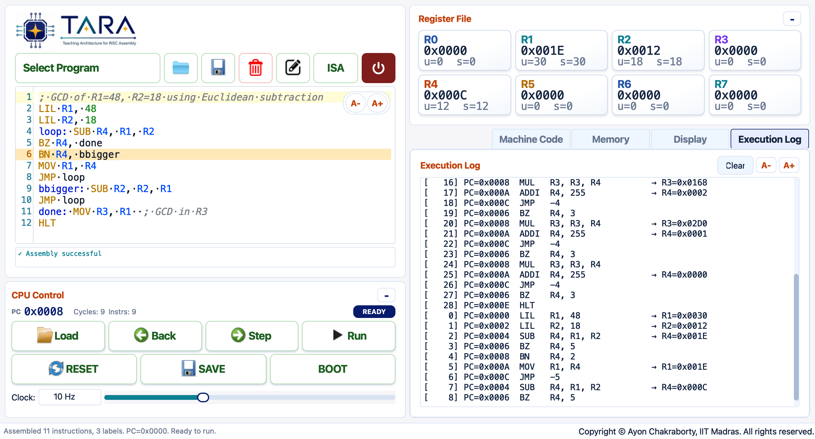
The Execution Log tab (GCD program, 9 steps). Each entry records the cycle number, program counter, instruction mnemonic, and every register that changed.
Reading the Execution Log
[ 0] PC=0x0000  LIL   R1, 6              -> R1=0x0006
[ 1] PC=0x0002  LIL   R3, 1              -> R3=0x0001
[ 2] PC=0x0004  MOV   R4, R1             -> R4=0x0006
[ 3] PC=0x0006  BZ    R4, done           (not taken)
[ 4] PC=0x0008  MUL   R3, R3, R4         -> R3=0x0006
The log holds up to 500 entries. Click Clear in the Execution Log tab to reset it.
Debugging Checklist
- Assembly errors — read the error box below the editor; it reports the line number and cause.
- Infinite loop — step through and watch whether the branch-condition register ever reaches zero or negative.
- Wrong memory values — jump to the data base address (e.g.
0x400) in the Memory tab. - Call returns to wrong address — inspect
R6beforeRETexecutes. - Stack corruption — initialize
R7to a stack address (e.g.0x500) before anyPUSH/POP.
Save & Boot Machine State
Save writes a complete snapshot to JSON: source code, assembled listing, all registers, PC, all 2048 memory bytes, halted flag, and execution counters. Boot restores any such snapshot, placing the CPU exactly where it was.
- Run a program to the point you want to preserve.
- Click Save and choose a filename (default:
local/config/cpu_state/tara_machine_state.json). - Later, click Boot and select that file.
- Continue stepping or running from the restored state.
TARA on Real Hardware Hardware
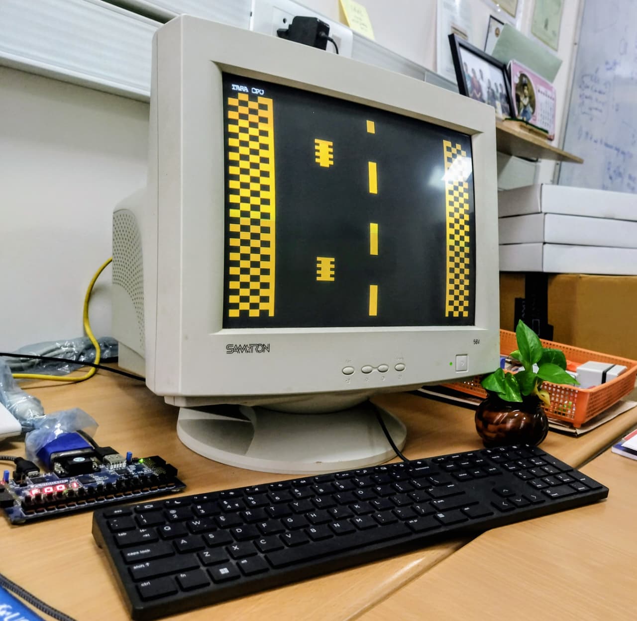
TARA is available not only as a software simulator, but also as a working digital hardware implementation. The same ISA can be synthesized onto an FPGA; on a Digilent Basys 3 board it operates as a small, self-contained computer. Once the bitstream is loaded, the board can boot a program directly, produce output on a VGA monitor, read input from a USB keyboard and the on-board controls, and expose its memory to TARA Studio over a single USB connection. Programs developed in the simulator, including examples such as Snake, Ping Pong, and Flappy Bird, can therefore be exercised on the physical processor.
The hardware setup is intentionally minimal: there is no operating system and no auxiliary processor responsible for executing the user program. The implemented system consists of the TARA CPU, 2 KB of memory, video output, and keyboard input. This makes the FPGA version a direct extension of the CS2300 design exercise: the same ISA studied in assembly and simulation is executed by a concrete hardware datapath that can be observed, debugged, and reprogrammed.
The following demonstration shows the complete TARA computer in operation. A game executes directly on the FPGA processor and produces live VGA output, while keyboard input controls the program and TARA Studio inspects and modifies the same hardware memory over USB.
The diagram below shows how the pieces connect. At the centre are the CPU and a single unified memory; everything else either feeds that memory, reads from it, or controls the processor.
The end-to-end TARA hardware system. The CPU and a single unified memory sit at the centre; the VGA scaler reads the framebuffer and drives a monitor, the directional buttons and USB keyboard land at 0x5FF, and TARA Studio reads and reprograms memory over the USB serial link.
The VGA display
TARA's picture is a tiny 64×64 framebuffer — one bit per pixel, living
in the top 512 bytes of memory (0x600–0x7FF). A dedicated
VGA scaler turns that into a picture a real monitor can show: a
standard 640×480 display refreshed 60 times a second. The scaler runs
completely on its own, independent of the CPU — for every point the monitor's beam is
painting, it works out which TARA pixel that corresponds to and whether it is lit.
Because the framebuffer is so much smaller than the screen, each TARA pixel is stretched
to cover a small rectangle — ten screen-pixels wide and seven tall — so the little
image grows to fill almost the whole display, drawn in a warm amber on a black
background. The CPU never has to think about video at all: it simply writes pixels into
memory, and the scaler does the rest. This is why the screen refreshes smoothly even
while you single-step the processor.
TARA Studio — live memory & debugging
So how do you peer inside a running chip? That is the job of the TARA FPGA Tool, the second tab of TARA Studio. It is the software companion to the hardware: over the same USB cable that programs the board, it gives you a live window into the running computer — read any part of memory while the CPU runs, watch it change in real time (heat-map and auto-refresh), write or poke values by hand, and assemble-and-load a brand-new program in seconds, with no re-synthesis and no rebuild. The same panel can also connect to Simulator Memory, which virtually attaches the memory tool to the local simulated CPU for debugging, demonstrations, or times when no FPGA board is available. Together, the board, simulator, and TARA Studio give you one workflow for inspecting and reprogramming TARA memory.
Connecting
Choose a Target first. Select FPGA USB to use a real board, pick the board's serial port from the Port dropdown (use Rescan if it is not listed), and press Connect. The tool pings the processor to confirm it is alive; on success the status turns green and the button becomes a red Disconnect. Select Simulator Memory and press Connect to attach the same tool to the simulator's current CPU memory.
no response, it is almost always the wrong port, the wrong baud rate, or a
bitstream that predates the USB memory bridge.
Reading & visualising memory
Enter a start address (hex) and a byte count, then click
Read. Memory is shown as a byte grid — address column, sixteen byte
columns (0–F), and an ASCII gutter you can drag wider. The
controls mirror the simulator's Memory tab:
| Control | What it does |
|---|---|
| Bytes | How many bytes to fetch (rounded up to whole 16-bit words on the wire). Defaults to the full 2 KB. |
| Hex / Dec | Switches every byte cell between hexadecimal and decimal. |
| Auto + ms | Re-reads the range continuously at the given interval, so you can watch memory change while the CPU runs. |
| Heatmap | Colours every byte by its value, making patterns visible at a glance. |
| A− / A+ | Shrink or enlarge the grid font. |
Between auto-reads, bytes that just changed are tinted green and the framebuffer region
(0x600 and up) is tinted gold, so live activity stands out.
Writing, filling & poking
The Fill bar writes a value (or random data, via the random checkbox) across a run of bytes — give it a start address, a byte count, and a 16-bit value. To change a single byte, just double-click its cell in the grid and type the new value.
Loading & running a program
Browse to a .tara source file and click
Load && Run. The tool assembles it, holds the CPU in reset,
streams the machine code to 0x000, and releases the CPU to run. With
FPGA USB, that transfer happens over USB with no re-synthesis. With
Simulator Memory, the same action loads the program into the local
simulated CPU, switches it to running state, and keeps the simulator registers, Memory
tab, Display tab, and execution controls in sync. The status line reports how many
instructions were loaded.
Running a program straight from the Simulator tab
You don't have to switch tabs to try code on the selected memory-tool target. Whenever the FPGA Tool is connected to either FPGA USB or Simulator Memory, the FPGA ▶ button in the Simulator tab's CPU Control bar lights up. Click it to assemble whatever is in the editor and run it in one step; the app switches to the FPGA Tool tab so you can watch the target memory. If the target is FPGA USB, the code is loaded over USB and runs on the board. If the target is Simulator Memory, the code is loaded into the local CPU and runs in the simulator. Until a target is connected, the button stays greyed out.
Bundled Programs
Load any program from the Select Program dropdown.
Programs are organised into five categories — the category name appears as a
section header in the dropdown.
Source files live in src/examples/progs/.
🟢 Basic
Single-loop programs that use only arithmetic and branching. Good first programs to step through.
| Program | Demonstrates | Result |
|---|---|---|
| Test Program | Minimal program to verify the assembler and CPU work. Loads two constants and adds them. | R2 = sum |
| Factorial Via Mul N 6 | Loop with MUL, ADDI -1, and BZ to branch on zero. Classic example of a counted loop. |
R3 = 0x02D0 (720 = 6!) |
| Fibonacci N 10 | Register moves, loop counter, and repeated ADD. Two accumulators walk the Fibonacci sequence. |
R6 = 0x0037 (55 = F₁₀) |
🔵 Intermediate
Uses more arithmetic instructions, nested loops, or conditional branches on negative.
| Program | Demonstrates | Result |
|---|---|---|
| GCD a=48 b=18 | Euclidean algorithm via subtraction. Uses BN to branch when a register goes negative. |
R3 = 0x0006 |
| Prime Test N=17 | Modulo-by-subtraction in a nested loop. Tests divisibility of each candidate from 2 to √N. | R2 = 1 (prime) or 0 |
| Generate Prime | Generates the first N primes and stores them as bytes. Uses CALL/RET for a sub-routine. |
First 10 primes at 0x0400 |
🟠 Advanced
Memory-intensive programs that use pointer arithmetic, arrays, and multi-word data structures.
| Program | Demonstrates | Result |
|---|---|---|
| Sort Insertion | Insertion sort on a byte array. Inner loop walks backward inserting the key using LDB/STB. |
Sorted bytes at 0x0400 |
| Sort Bubble | Bubble sort with a swap flag for early exit. Good comparison to insertion sort. | Sorted bytes at 0x0400 |
| Binary Search | Binary search on a sorted byte array using SHR for midpoint. R0=base, R1=length, R2=key. |
R3 = 3 (index of key 7) |
| Matrix Multiplication | 3×3 byte-matrix multiply. Three nested loops with pointer arithmetic and word-size result storage. | Result matrix at 0x0440 |
🟣 Display
Graphical programs that draw to the 64×64 framebuffer. Run them on the Display tab.
| Program | What it draws | Clock |
|---|---|---|
| Draw Line | Bresenham-style line from one corner to another. Demonstrates per-pixel bit-mask addressing. | Any — runs once then halts |
| Draw Rectangle | Filled or outlined rectangle. Uses byte-aligned writes for horizontal spans. | Any — runs once then halts |
| Draw Triangle | Filled triangle using scanline fill. Good introduction to two-pointer drawing. | Any — runs once then halts |
| Draw Spiral | Rectangular spiral drawn incrementally — each side is one loop iteration. | Any — runs once then halts |
| Paint Image | Copies a pre-loaded glyph from data memory into the framebuffer. Pair with the Import Image tool. | Any — runs once then halts |
| Display Bouncing Ball | Glyph-blitter animation — loads a 16×16 sprite from 0x0400 and bounces it around the canvas. Import a custom glyph first to replace the default circle. |
300–1 000 Hz |
🔴 Games
Fully interactive games controlled via the keyboard register at 0x05FF. Open the Display tab, click the canvas to give it focus, then click Run.
| Program | Controls | Speed |
|---|---|---|
| Snake | ↑↓←→ / WASD to steer. Q to quit. | ~1 kHz |
| Ping Pong | ←→ / AD to slide the bat. Q to quit. | ~1–2 kHz |
| Flappy Bird | Tap / hold ↑ / W to flap. Q to quit. | ~4–8 kHz |
| Racing | ←→ / AD to change lane. Q to quit. | ~1–2 kHz |
Microarchitecture Advanced
This section opens the hood. If you want to build TARA yourself — in Logisim, in Verilog, or even on paper — here is the picture to keep in front of you. TARA is a multi-cycle, microcoded processor: every instruction is carried out as a short sequence of tiny steps, and a small read-only memory (the microcode) decides what each step does. Nothing is mysterious — the whole machine is a handful of registers, one ALU, one memory, and a table that tells them when to move.
The complete TARA16 datapath (blue) beneath its microprogrammed control unit (maroon) — drawn to match rtl/cpu/tara_cpu.v signal for signal. Every maroon tag names the control-word field that drives that register, mux or memory port, so the diagram doubles as a wiring list: build each block, then connect the 40-bit control word to the tags. Note the two things students most often get wrong — IR is loaded from MDR (not straight from memory), and branches test register-file Port A directly through an independent comparator, never through the observational Z/N/C/V status register.
The datapath — the parts that move data
The core building blocks are standard components that can also be reproduced in Logisim:
| Block | What it is |
|---|---|
| PC | Program counter (a register). Holds the byte address of the next instruction; bumps by 2 each fetch, or is loaded with a branch/jump target. |
| IR | Instruction register. Holds the fetched instruction; its opcode field drives the control unit, and its immediate/offset fields feed the ALU's B input. |
| MAR / MDR | Memory address & data registers — the latches that talk to memory. MAR retains the low 11 bits of the byte address; MDR holds the 16-bit value read from memory or selected from register-file Port B for a store. |
| Register File | R0–R7, with two read ports (A, B) and one write port. The write-address mux selects the encoded destination, R6, or R7; the write-data mux selects the ALU result, MDR, LIL/LIH immediate construction, or PC link value. |
| ALU | The calculator: ADD, SUB, MUL, AND, OR, XOR, NOT, SHL, SHR, SLT (plus pass-through). Input A is Port A or the PC; input B is Port B or one of the immediate/offset values. |
| Branch Comparator | Tests register-file Port A directly for zero or a set sign bit. It gates conditional PC loads for BZ and BN and does not read the status register. |
| Status | The observational flag register: Zero, Negative, Carry, and Overflow, latched from selected ALU operations for LEDs/debug. It is not architecturally visible and never controls a branch. |
| Unified Memory | 2 KB (1024 × 16). The same array holds code, data, the stack, the live input byte at 0x5FF, and the framebuffer at 0x600–0x7FF that the VGA hardware paints. |
The control unit — the part that decides
TARA does not decode instructions with a tangle of hand-drawn logic gates. Instead a
ring counter ticks through step numbers T0…T7, and a
small Control ROM — addressed by {opcode[4:0], Tstate[2:0]}
— outputs one 40-bit control word per step. Each bit (or small field)
of that word is wired to exactly one thing in the datapath: a register's load-enable,
a mux's select field, the ALU's operation, or the memory write-enable. Run the steps in
order and the instruction happens. A done bit in the word resets the ring
counter back to T0 to start the next instruction.
One instruction, step by step
Every instruction begins with the same three fetch steps, then runs its own short execute sequence:
- T0 —
MAR ← PC(point memory at the next instruction) - T1 —
MDR ← Memory[MAR];PC ← PC + 2 - T2 —
IR ← MDR(now the opcode is known, so the ROM can pick the right execute steps)
Then, for example:
ADD Rd, Ra, Rb— T3: ALU computesRa + Rb, result written toRd, flags updated,done.LDW Rd, off(Rb)— T3:MAR ← Rb + off(ALU); T4:MDR ← Memory[MAR]; T5:Rd ← MDR,done.BZ Rt, label— T3: the independent Port-A comparator testsRt == 0; if true, the ALU resultPC_after + (sext8(offset)×2)loads the PC, thendone.
Building it in Logisim
- The ALU first. Make a 1-bit full adder, chain 16 of them into an adder, then add the logic/shift/compare operations and an op-select mux. Test it on its own before wiring anything else.
- The registers. Drop in PC, IR, MAR, MDR and the eight-register file (registers + read/write-port muxes). Give each its load/enable input.
- Wire the datapath as shown above: Port A or PC feeds ALU input A; Port B, signed offsets/immediates, constant 2, the scaled branch displacement, or shift amount feeds input B. Route the ALU result to MAR, PC, and the register write-data mux; route MDR and immediate/link sources through that write-data mux; and route Port B through MDR for stores.
- The control word is just a bundle of wires. Put the microcode in a Logisim ROM component addressed by
{opcode[4:0], Tstate[2:0]}(an 8-bit address, 256 entries) with a 40-bit output; split that output and route each field to the load/select line it controls. - The clock & stepping. A counter + decoder gives you T0–T7; reset it to T0 when the
donebit is set. Use Logisim's clock (and single-step) to walk through the T-states and watch the registers update.
You do not have to invent the control words: tools/microcode/gen_microcode.py
in the Verilog project emits the exact 256-entry ROM image, shared field definitions, and a readable listing of
which signals each step asserts — a perfect answer key. And the software simulator (or
the cycle-accurate hardware model in tools/model/) is your verification reference: load
the same program in both, single-step, and confirm the registers and memory match.
Troubleshooting
| Symptom | Cause & Fix |
|---|---|
No module named 'PyQt5' |
Run pip install PyQt5 in the same Python environment you use to launch the app. |
| Heatmap checkbox is disabled | Matplotlib is not installed. Run pip install matplotlib. |
| Assembly fails: unknown mnemonic | Check the spelling against the ISA dialog (click ISA in the editor toolbar). |
| Invalid memory operand error | Memory syntax must be offset(Rbase). Use 0(R0), 2(R0), -1(R4). |
| Program never halts | Step through the loop and watch the branch-condition register. Verify it eventually reaches zero or negative. |
| Data is overwritten by code, or vice versa | Keep instructions near 0x000, arrays near 0x400. Initialize R7 before any stack use. |
| Cell edit produces an unexpected value | Bare values in the inline editor that contain only hex digits are parsed as hex. Use explicit 0x, 0b, or decimal prefixes. |
Appendix
Quick Opcode Index
All mnemonics at a glance:
Data move:    MOV  LIL  LIH
Memory:       LDW  STW  LDB  STB
Arithmetic:   ADD  SUB  MUL  ADDI
Logic:        AND  OR   XOR  NOT
Shift:        SHL  SHR
Compare:      SLT
Branch:       BZ   BN
Jump/Call:    JMP  CALL  RET
Stack:        PUSH  POP
System:       NOP  HLT
File Paths
| Path | Purpose |
|---|---|
src/examples/progs/ | Bundled example programs (shown in the Select Program dropdown). |
local/config/memory/memory_dump.csv | Default CSV export destination. |
local/config/cpu_state/tara_machine_state.json | Default save/boot path for machine state. |
Copyright © 2026 Ayon Chakraborty, SENSE Lab, IIT Madras.